The Canadian Guitar Forum banner
21 - 40 of 54 Posts
None of those schematics include a transformer and none of the images provide sufficient detail to produce an accurate schematic, without the schematic it's speculation. I don't believe that they are using the transformer as an inductor...how else are they tripling the signal out as noted in post#12.
 
Discussion starter · #22 ·
and another... just so they are all in the same place

Image
 
Discussion starter · #29 ·
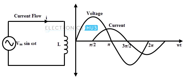
learning more about what inductors do in AC circuits, their generated signal will lag the input signal by 90 degrees, or a quarter phase. A signal boost plus a phase shift.

.
 
I'm not so sure the schematic Paul shows is accurate. I can't see where the role of transformer in that drawing would increase the amplitude of the output signal. It would certainly alter the tone, but as drawn does not seem to impose any noteworthy level shift in the level.

The Les Paul Recording guitar also includes a transformer. However, its role is to turn the low-impedance pickups into a higher-impedance output, such that it can either be used direct into the board (where the normal low impedance is similar to what a voice mic would be), OR it can feed a regular old guitar amp.

To be honest, I'm kinda stumped here.
 
it's meant to be a low to mid boost of 6db. You can really hear it when he turns on the boost with the bridge pickup.
 
  • Like
Reactions: Paul Running
Phil McKnight's decription would suggest otherwise. That's not to suggest you're wrong, because yes cutting mids and bass would indeed reduce overall level. But Phil describes it as a "passive boost", and NOT simply an apparent boost when something affecting level is removed. If the schematic IS accurate, then that would suggest Phil may not "know his gear" as well as he thinks in this particular instance.

I don't say this to throw stones at Phil, or anyone else. Either the schematic is correct and knightyyz is accurate in his description, or Phil misunderstood (perhaps as a result of bad ad copy from Yamaha).
 
to me when he pulls the knob you can hear more mids and bass. So not cutting the mids/bass but boosting those frequencies only. Especially on the bridge pickup. mhammer you mentioned it alters tone and to me you nailed it too because it does alter how the bridge reacts. It is definitely altering the tone by only boosting part of the signal.
 
Discussion starter · #36 ·
I've been reading a lot about inductors. Come to the rabbit hole with me...


What I found really fascinating about this is that an inductor will have a real variety of effects on the signal and they will differ at different frequencies, which implies they must have really tuned that inductor to the rest of the circuitry - pickups, caps, pots and all (mod at your peril).

What I understood from that site was the fact that the inductor has a resonant frequency which is a function of its physical characteristics (winding mostly). Below that frequency it will act as an inductor, above it a capacitor. Given that a pickup signal will have a really wide range of frequencies, all of these effects will be happening at once.

The one thing that seems immutable is the phase shift of 90 degrees between the input voltage and output current.

None of this really helps me build one - and now I really want to. And I am not sure I can quite explain the mid/low boost which is definitely there in all the sound checks I have watched, and there are many.

One of us has to go and distract the guy at long and mcquaid while someone else grabs one off the wall, whips the cover plate off and draws a wiring diagram. It's the only way we are going to get an answer.
 
Discussion starter · #37 ·
Unable to sleep, and unable to put this down, I continued looking at the low pass question and found this...


"An ideal inductor would not behave like a capacitor, but in the real world there are no ideal components.

Basically, any real inductor can be though(t) of (as) an ideal inductor that has a resistor in series with it (wire resistance) and a capacitor in parallel with it (parasitic capacitance).

Now, where does the parasitic capacitance come from? an inductor is made out of a coil of insulated wire, so there are tiny capacitors between the windings (since there are two sections of wire separated by an insulator). Each section of windings is at a slightly different potential (because of wire inductance and resistance).

As the frequency increases, the impedance of the inductor increases while the impedance of the parasitic capacitor decreases, so at some high frequency the impedance of the capacitor is much lower than the impedance of the inductor, which means that your inductor behaves like a capacitor. The inductor also has its own resonance frequency.

This is why some high frequency inductors have their windings far apart - to reduce the capacitance."
 
I believe that understanding the effects of the Quality factor of an inductor will help too. If they are using that transformer as a parallel inductor, the Q factor will be low...this may be intentional for a wider bandwidth, at the expense of boost.
So what do you believe is the purpose of this circuit?

There's one for sale on this forum
 
Discussion starter · #39 ·
Q is proportional to L / R, so improving it either means increasing inductance (by, say, adding a better ferromagnet in the coil so it stores magnetic energy better) or reducing R (maybe reducing turns? Thicker wire?)

My guess is that they would probably want as wide a range of frequencies as possible, but the audio tests reveal it’s clearly being skewed to lower frequencies. This strengthens the argument in my opinion that this is very carefully tuned to the rest of the electronics in the guitar.

You ask the right question Paul, what’s it for? I think it does triple duty amplifying the signal, acting as a low pass filter and shifting the phase.
 
The schematic Paul shows indicates an LCR filter - a variable resistance in series with a capacitor and inductor. The typical result of that is a bleeding of spectral content above some point and below some other point. This is precisely what the old Varitone circuit did/does, except that in this instance, there is only one capacitor value, in tandem with a way to vary the resistor. The Varitone has a fixed amount of cut, but switches between different capacitor values to move the focal point and width of the mid-cut around.

Here's Craig Anderton's "Passive Tone Circuit" - an adaptation of the Varitone as a single passive pedal, from his 1980 book, Electronic Projects for Musicians. He uses one side of a small interstage transformer as an inductor, with a switch to double/halve the inductance, a rotary switch to select between capacitor values, and moves the variable resistance after the inductor, instead of before the capacitor as in the Revstar circuit. I built one into a pedal, in conjunction with a single FET booster stage, to compensate for the passive loss. I realized that by bypassing the inductor, it would become a treble cut, by bypassing the capacitors become a bass cut, and by bypassing both the caps and inductor, a simple attenuator. So I made that all switchable, turning it into a very flexible tool.

In an older document I got from Dan Torres, he also has a circuit for a bidirectional tone control. One side from the midpoint is normal treble-cut, and the other direction of rotation has a cap in series with an inductor to ground, providing a variable mid-cut. I can credit Yamaha for including such a circuit, in order to make an otherwise standard 2-pickup/two-knob guitar a little more flexible. But credit for the circuit itself has to go to many people before Yamaha.
Image
 
21 - 40 of 54 Posts