The Canadian Guitar Forum banner

Deluxe Reverb (AB763 circuit) Issue - Solved

1 reading
8.2K views 113 replies 8 participants last post by  _Knighthawk_  
#1 ·
Hi all,

I'm experiencing a challenge with a current build. The two primary symptoms I have identified thus far:

1) Channel 2 (Vibrato channel) is acting erratically. When I apply any volume on the pot, I almost immediately get wild hum at fairly high volume. Channel 1 seems pretty good - although there is some high frequency ringing when I apply instrument signal. Both channels are extremely quiet until signal is applied.

2) My voltage reading on Pin 1 of V5 seems to be way out of whack. I believe I should be expecting ~210V but I'm seeing 460V. It is possible that the original high definition drawing is calling for ~270V - can't tell if that is a one or a seven after the 2 - but either way, I don't think I should be seeing 460V. As you can see from the image, it is receiving power B+2 power from the board via the 220K resistor.
Image


My guesses thus far are that there may be a grounding problem so I have double- and triple-checked all ground connections. No issues there. I also tried swapping out tubes (I've gotten as far as V3). I have tested the sweep in the 1meg volume pot and swapped out the shielded cable from the channel 2 jack. Anyway, this is a bit of a mystery to me. Anyone have any ideas?
 
#3 · (Edited)
Schematic


Layout


Make sure the lead from the doghouse is on the left side of the 220k. Also make sure the 220K is correct. Could be a 22k and not doing it’s job.

Also, make sure the lead from pin 7 is going to the right point with a continuity test.

Actually, make sure everything on the vibrato section is in the right place. Make sure both the left and middle tab of the speed pot are grounded by the 100-120k resistor.

Image
 
#6 ·
Schematic


Layout


Make sure the lead from the doghouse is on the left side of the 220k. Also make sure the 220K is correct. Could be a 22k and not doing it’s job.

Also, make sure the lead from pin 7 is going to the right point with a continuity test.

Actually, make sure everything on the vibrato section is in the right place. Make sure both the left and middle tab of the speed pot are grounded by the 100-120k resistor.

View attachment 471316
I have verified the 220K resistor more than once (I measure each resistor before it goes on the board but this doesn't mean I haven't made this mistake!).

I can verify that the lead from pin 7 originates from the correct location (continuity tested on completion and again now - I dot these as in the image below.

Image


I can verify that there there is a 100k resistor connected to ground bus from lugs 2 and 3 of the (3M RA) speed pot.

Thanks for the drawings! They are bit clearer than the Fender ones I was using (pin 1 should be 270 V).
 
#10 ·
The voltage drops from 475V to 382V. That said, the voltage really jumps around a lot on
I am curious about the coiled, red-insulated wire in the image.
View attachment 471327
The coiled red wire is not connected to the circuit. It is merely extra shielding around the three (twisted) wires coming out of the doghouse. The idea (according to my research - this wasn't my idea) was to shield those wires from the wiring that goes up to the pots in the vibrato channel preamp section. I cannot say to what extent this may or may not be effective since this is the first time I have done it and I don't yet have a fully functional circuit. That said, a primary goal is to make these amps as quiet as possible (which is very challenging in channel 2 of the DR).
 
#12 ·
Here's a link to video/audio of what i am hearing and seeing:


As an aside, when I go to drain the caps at the B+1 junction, I am seeing a bit of an arc (wee spark). That can't be good, of course, but I am concerned that it might mean something that I haven't the experience to ascertain.
 
#15 ·
As an aside, when I go to drain the caps at the B+1 junction,
What value of discharge resistance are you using?
Reservoir or filter caps in most deluxe-sized tube amps, store immense amount of electrical energy. If the resistance to ground is low, she's going to spark, at those high voltages.
 
#34 ·
Incidentally, I swapped out the 220K and reflowed both sides of the connection (reseated the 10 meg as well).

Nothing new to report. Still screams at 2 on the volume pot and sounds like I'm tuning in a top 40 station from Neptune.

Edit: On the upside. Channel 1 sounds pretty much like ti should. :)
 
#35 · (Edited)
may be off base here.....you describe what could result from a reversed feedback loop...unsolder the 820R running from the speaker jack tip(where yellow meets green) to the post pi network and listen for a difference....cant hurt to try...if it is improved then switch the speaker jack wires(the green and black) from the output tranny and rehook the feedback loop(the 2nd channel has an extra triode in use and the signal is inverted from the normal channel).
this should not affect the V4 pin 1 voltage issue....still..
Image
 
#38 ·
may be off base here.....you describe what could result from a reversed feedback loop...unsolder the 820R running from the speaker jack tip(where yellow meets green) to the post pi network and listen for a difference....cant hurt to try...if it is improved then switch the speaker jack wires(the green and black) from the output tranny and rehook the feedback loop(the 2nd channel has an extra triode in use and the signal is inverted from the normal channel).
this should not affect the V4 pin 1 voltage issue....still..
I'm willing to give this a try but I'm not sure exactly how to do what you are suggesting.

You want me to unhook the 820R and hook the speaker jack directly it into the 47ohm/22k ohm/.1uf shunt cap junction?

Question: Would that not invert channel 1?
 
#43 · (Edited)
Not sure if anyone is interested or not but just in case:

Sharing my parts list for this build...

ItemBrand/SourceCOSTSOURCE
Power TransformerHammond 291BX
$163.99​
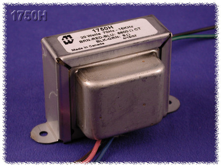
Output TransformerHammond 1760H
$93.99​
ChokeHammond 194A - Choke - 4H, 50mA
$31.99​
Hammond 194A - Choke - 4H, 50mA
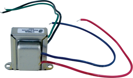
Reverb DriverHammond 1750A - Output Transformer - 25K, 8 OHM, SE, 3.5W
$46.99​
CabinetVeteran Guitars
$400.00​
Veteran Guitar Cabinets (see Facebook)
TubesPremium Package
$445.70​
Chassis +Boards, Doghouse Pan, Faceplates, Footswitch, Knobbies
$450.00​
MOJO - includes $75 shipping
Reverb TankMOD 4AB3C1B
$57.00​
Nextgen
Reverb Tank Bag17"
$20.99​
Nextgen
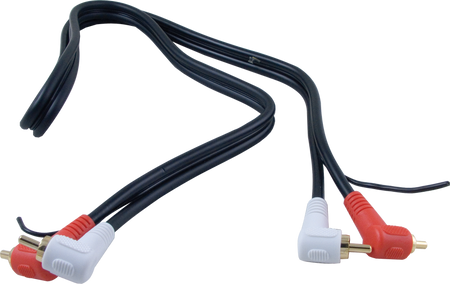
RCA Jacks
$10.19​
Legend 1258Eminence (client's choice of speaker)
$166.39​
ComponentsPassive components and hardware-NextGen
$355.00​
(Pots, jacks, switches, tube sockets, lamp, capacitors, etc.)

A big shout out to the folks at NextGen Guitars! They're a Canadian outfit located in Ottawa (Nepean). Reasonably priced components, outstanding customer service (I think the owner, Jonathan Beals is a GC member). I also have to acknowledge and pass along kudos to Derrick Bell at Veteran Guitar cabs (some of you probably know Derrick) for his great work on the blackface cabs he builds for me. He is kind enough not to chuckle at me when I ask him about my crazy design ideas.
 
#47 ·
So, I'm still having issues with voltage.

I'm seeing B+2 voltage of 490VDC coming out of the doghouse and going to the reverb driver. This is definitely high since the 12AT7 at V3 is expecting to see ~410V. Any ideas why my B+2 is so high?

Incidentally, I've got 490VDC going to the plates in the power tubes (V6 and V7).

I'm at a loss here. Is it possible I have blown 10K resistors? A leaking or open cap? Any ideas?

EDIT: My mains are stupid high (126VAC)..
 
#59 ·
I confess that I don't understand why we bother running wires in and out of the doghouse for B+2 since we could pull exactly the same B+2 voltage from the mainboard off of the choke. It seems like a silly exercise to me since it's B+2 no matter where you get it from. Is it to prevent interference on the long run to the V3 and V5 plates?

EDIT: Wife wants me to break for dinner. I didn't even realize it was that time!